Pinout & Connectors
Complete pin assignments and connector reference for the H7-Digital flight controller, including all connectors, motor outputs, UARTs, and special functions.
Table of Contents
- Quick Reference
- UART Mapping
- Power System
- Connectors
- Motor Outputs (M1-M8)
- Servo Outputs (S1-S2)
- Understanding ESC Telemetry Methods
- I2C Ports
- SPI Ports
- ADC Inputs (Analog Sensing)
- GPIO and Special Functions
- Board Orientation and Mounting
- Wiring Best Practices
- Solder Pads (Alternate Connections)
- Troubleshooting Connection Issues
- Connector Standard
- Cable Compatibility Matrix
- Related Documentation
- External Resources
- Support
Quick Reference
Board Specifications
| Specification | Value |
|---|---|
| Board Size | 41mm × 41mm |
| Mounting Holes | M3 (4 holes) |
| Mounting Pattern | 30.5mm standard spacing |
| Connector Standard | JST-SH - Betaflight Connector Standard |
| Signal Voltage | 3.3V logic |
Pinout Diagrams
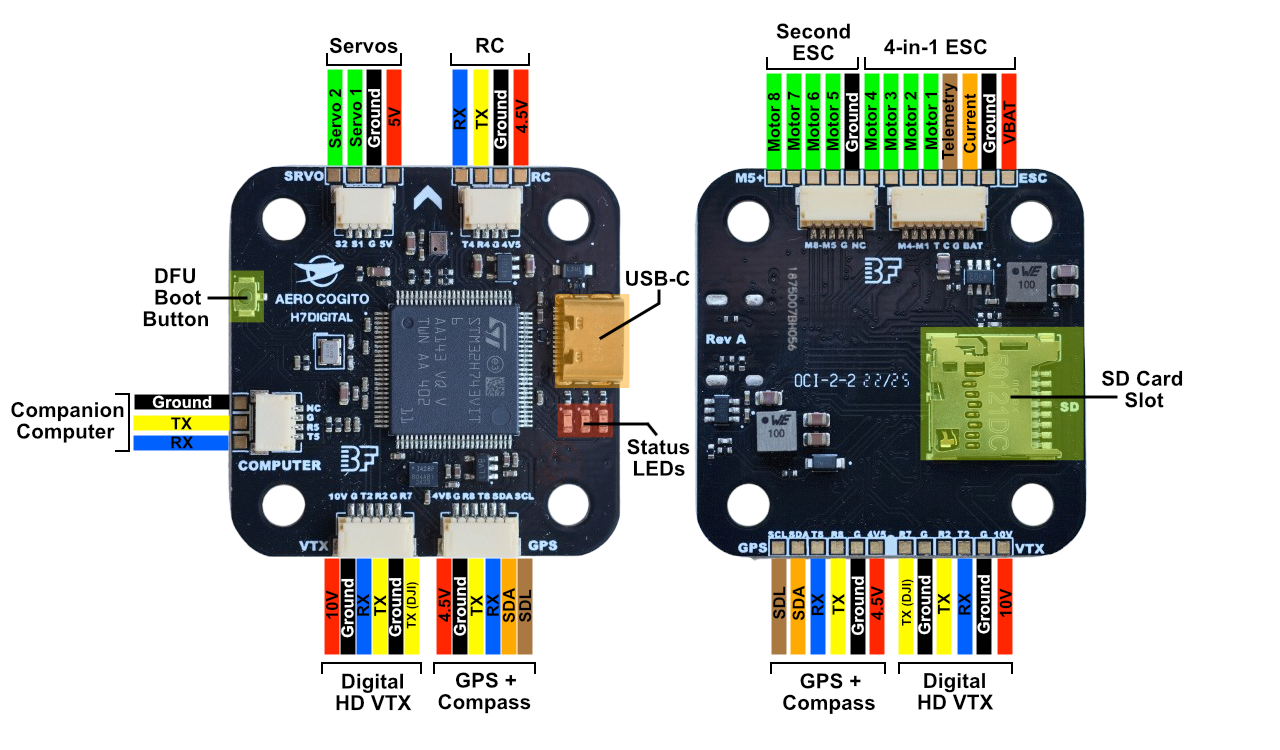
Click image to view full size
Labeled wiring diagram showing all connector locations and pin assignments
The arrow on the board indicates the forward direction of the aircraft. Orient your flight controller with the arrow pointing toward the front of your vehicle.
UART Mapping
Complete UART Reference
| UART | TX Pin | RX Pin | Default Protocol | DMA (ArduPilot) | DMA (Betaflight) | Connector/Location | Primary Use |
|---|---|---|---|---|---|---|---|
| UART2 | PA2 | PA3 | DisplayPort (42) | ✓ | ※ | VTX connector | MSP OSD to digital VTX |
| UART3 | - | PD9 | ESC Telemetry (16) | ✗ | ※ | ESC connector Pin 4 | ESC RPM/voltage/current (RX only) |
| UART4 | PD1 | PD0 | RCIN (23) | ✓ | ※ | RC connector | SBUS/CRSF/ELRS receiver |
| UART5 | PB13 | PB12 | MAVLink2 (2) | ✓ | ※ | COMPUTER connector | Raspberry Pi/Jetson |
| UART7 | - | PE7 | None (0) | ✓ | ※ | VTX connector R7 | DJI SBUS input (RX only) |
| UART8 | PE1 | PE0 | GPS (5) | ✓ | ※ | GPS connector | GPS module |
DMA Configuration:
- ArduPilot: UART3 RX (ESC Telemetry) has DMA explicitly disabled. This is intentional for ESC telemetry, which defaults to a low 10Hz update rate. Without DMA, each received byte triggers a CPU interrupt. At 10Hz with 10-byte packets (100 bytes/sec at 115200 baud), interrupt overhead is negligible. DMA would provide no benefit at such low data rates, and the NODMA configuration frees up DMA channels for higher-bandwidth peripherals.
- Betaflight: All UART DMAs are disabled by default to avoid DMA resource conflicts with bidirectional DShot. Betaflight prioritizes bidirectional DShot (400Hz motor telemetry) over UART DMA. (※ = Conditionally available when bidirectional DShot is disabled or on non-conflicting DMA streams)
ArduPilot Protocol Numbers
Common SERIALx_PROTOCOL values:
- 0 = None (disabled)
- 2 = MAVLink2 (telemetry/companion)
- 5 = GPS
- 16 = ESC Telemetry
- 23 = RC Input (SBUS/CRSF/etc.)
- 42 = MSP DisplayPort (OSD)
Power System
Battery Input
| Connection | Location | Voltage Range | Notes |
|---|---|---|---|
| VBAT | ESC connector Pin 1 | 9.9V-25.2V (3S-6S LiPo) | Main power input |
| GND | ESC connector Pin 2 | Ground | Common ground |
Regulated Power Outputs
| Output | Voltage | Current | Available On | Purpose |
|---|---|---|---|---|
| 5V | 5.0V | 2.5A peak, 2A continuous | SRVO connector | Servo power (VBAT only) |
| 4.5V | 4.5V nominal | 2.5A peak, 2A continuous | RC Input, GPS connectors | Peripherals (USB or VBAT) |
| 10V | 10.0V | 2.5A peak, 2A continuous | VTX connector only | Digital HD VTX power |
5V and 4.5V Rails Share Same BEC: Both the 5V and 4.5V outputs are powered from the same 5V BEC (2A continuous, 2.5A peak total). The difference:
- 5V rail: Direct BEC output (5V pads, e.g SRVO connector) - only powered when VBAT is connected
- 4.5V rail: BEC or USB power auto-select (RC Input, GPS connectors) - powered when either USB is connected or VBAT
10V Output is VTX Only: The 10V BEC is designed exclusively for digital HD video transmitters. Do NOT connect standard 5V peripherals to the 10V output. Damage will occur.
USB Power for Bench Testing: The 4.5V rail is powered from either USB or battery (auto-select). You can test the flight controller with GPS, compass, and RC receiver via USB power alone (no battery required).
Connectors
ESC Connector (8-pin JST-SH)
Location: Bottom side, top edge, right Connector Type: 8-pin JST-SH
| Pin | Label | Signal | STM32 Pin | Timer | Voltage | Function |
|---|---|---|---|---|---|---|
| 1 | BAT | VBAT | - | - | 9.9V-25.2V | Battery positive (3S-6S LiPo) |
| 2 | G | GND | - | - | Ground | Battery negative / common ground |
| 3 | C | Current | PA1 | ADC1 | 3.3V analog | Current sensor input from ESC |
| 4 | T | Telemetry | PD9 | UART3 RX | 3.3V UART | ESC telemetry (RX only) |
| 5 | M1 | Motor 1 | PE9 | TIM1_CH1 | 3.3V PWM | Motor 1 signal |
| 6 | M2 | Motor 2 | PE11 | TIM1_CH2 | 3.3V PWM | Motor 2 signal |
| 7 | M3 | Motor 3 | PE13 | TIM1_CH3 | 3.3V PWM | Motor 3 signal |
| 8 | M4 | Motor 4 | PE14 | TIM1_CH4 | 3.3V PWM | Motor 4 signal |
Default Protocols:
- Motor signals: DShot600 (recommended) or DShot300
- Telemetry: ESC telemetry protocol (RX only on T pin) OR bidirectional DShot (on motor signal wires)
Configuration:
- ArduPilot:
SERIAL5_PROTOCOL = 16(ESC Telemetry) - Betaflight: Ports tab → Enable “ESC” on UART3
Included Cable:
- 1x JST-SH 8-pin to JST-SH 8-pin cable (for 4-in-1 ESCs)
4-in-1 ESC Connection: Always double-check that the intended ESC pinout matches the H7-Digital ESC pinout before using the included 8-pin JST-SH ESC connector. Manufacturers often use different/incompatible pinout standards.
ESC Telemetry Options: The H7-Digital supports three telemetry methods: UART-based ESC telemetry (via Pin 4), bidirectional DShot (via motor signal wires, RPM only), or Extended DShot Telemetry/EDT (via motor signal wires, comprehensive data). See Understanding ESC Telemetry Methods below for detailed comparison and configuration.
Wiring Notes:
- Wire gauge: 22-24 AWG for ESC-to-FC connection (standard JST-SH pre-wired cables at <30mm length)
- Motor signals: Keep as short as possible (≤15cm recommended)
- Signal integrity: Route motor signal wires away from high-current VBAT wires
Motors 5-8 Connector (6-pin JST-SH)
Location: Bottom side, top edge, left Connector Type: 6-pin JST-SH
| Pin | Label | Signal | STM32 Pin | Timer | Voltage | Function |
|---|---|---|---|---|---|---|
| 1 | NC | Not Connected | - | - | - | Reserved (no connection) |
| 2 | G | GND | - | - | Ground | Common ground |
| 3 | M5 | Motor 5 | PD12 | TIM4_CH1 | 3.3V PWM | Motor 5 signal |
| 4 | M6 | Motor 6 | PD13 | TIM4_CH2 | 3.3V PWM | Motor 6 signal |
| 5 | M7 | Motor 7 | PD14 | TIM4_CH3 | 3.3V PWM | Motor 7 signal |
| 6 | M8 | Motor 8 | PD15 | TIM4_CH4 | 3.3V PWM | Motor 8 signal |
Use Cases:
- Octocopter / X8 configurations (8 motors total)
- Hexacopter + camera gimbal control
- Additional motor outputs for VTOL/tiltrotor
No Power Pin: This connector does not provide power from the second ESC.
RC Input Connector (4-pin JST-SH)
Location: Top side, top edge, right Connector Type: 4-pin JST-SH
| Pin | Label | Signal | STM32 Pin | Voltage | Function |
|---|---|---|---|---|---|
| 1 | 4V5 | Power | - | 4.5V @ 2A | Receiver power (from 5V BEC or USB) |
| 2 | G | GND | - | Ground | Common ground |
| 3 | R4 | RX | PD0 | 3.3V UART | Receiver signal input (UART4 RX) |
| 4 | T4 | TX | PD1 | 3.3V UART | Receiver telemetry output (UART4 TX) |
Supported Protocols:
- SBUS (FrSky, Futaba)
- CRSF (TBS Crossfire)
- ELRS (ExpressLRS)
- DSM/DSMX (Spektrum)
- PPM (legacy)
Configuration:
- ArduPilot:
SERIAL4_PROTOCOL = 23(RC Input) - Betaflight: Receiver tab → Serial-based receiver
Bidirectional Protocols: CRSF and ELRS support telemetry back to the transmitter (battery voltage, GPS, RSSI). Connect both RX and TX for full bidirectional communication.
USB Power for Bench Testing: The RC connector is powered from the 4.5V rail (5V BEC or USB). You can test RC binding via USB power alone (no battery required).
SRVO Connector (4-pin JST-SH)
Location: Top side, top edge, left Connector Type: 4-pin JST-SH
| Pin | Label | Signal | STM32 Pin | Timer | Voltage | Function |
|---|---|---|---|---|---|---|
| 1 | 5V | Power | - | - | 5V @ 2A | Servo power (from 5V BEC) |
| 2 | G | GND | - | - | Ground | Common ground |
| 3 | S1 | Servo 1 | PC6 | TIM3_CH1 | 3.3V PWM | Servo 1 signal (PWM output 9) |
| 4 | S2 | Servo 2 | PC7 | TIM3_CH2 | 3.3V PWM | Servo 2 signal (PWM output 10) |
Applications:
- Camera gimbal (pan/tilt)
- Landing gear retraction
- Parachute deployment
- Cargo drop mechanisms
- Control surface mixing (for fixed-wing/VTOL)
PWM Frequency: Configurable 50Hz-490Hz (50Hz standard for analog servos)
Current Draw: The 5V BEC supplies up to 2A continuous (shared with 4.5V rail total). High-torque servos or multiple servos under load can exceed this limit. Monitor current draw and consider external BEC if needed.
GPS/Compass Connector (6-pin JST-SH)
Location: Top side, bottom edge, right (solder pads on opposite side of the board) Connector Type: 6-pin JST-SH
| Pin | Label | Signal | STM32 Pin | Voltage | Function |
|---|---|---|---|---|---|
| 1 | 4V5 | Power | - | 4.5V @ 2A | GPS/compass module power (USB or VBAT) |
| 2 | G | GND | - | Ground | Common ground |
| 3 | R8 | RX | PE0 | 3.3V UART | GPS data input (UART8 RX) |
| 4 | T8 | TX | PE1 | 3.3V UART | GPS data output (UART8 TX) |
| 5 | SDA | I2C Data | PB7 | 3.3V I2C | Compass data (I2C4 SDA) |
| 6 | SCL | I2C Clock | PB6 | 3.3V I2C | Compass clock (I2C4 SCL) |
Configuration:
- ArduPilot:
SERIAL3_PROTOCOL = 5(GPS), I2C compass auto-detected - Betaflight: Ports tab → GPS on UART8, Compass auto-detected on I2C4
Compatible GPS Modules:
- u-blox M8 (2014 generation, budget-friendly)
- u-blox M9 (2019 generation, improved accuracy)
- u-blox M10 (2020+ generation, fastest fix times - recommended)
- GPS + Compass combo (e.g., Holybro M9N, Matek M10-5883)
Compass Recommended for ArduPilot: While ArduPilot allows compass-less operation in certain modes (e.g., GUIDED_NOGPS for companion computer control), a compass or alternative heading source is typically required for proper navigation and autonomous operation. The H7-Digital has no onboard compass. Use a GPS/compass combo module for full functionality.
USB Power for Bench Testing: The GPS connector is powered from the 4.5V rail (5V BEC or USB). You can test GPS lock and compass calibration via USB power alone (no battery required).
I2C Pull-ups: The board includes on-board I2C pull-up resistors. If using long cables (>30cm) or multiple I2C devices, you may need to adjust I2C speed to 400kHz (see I2C Ports).
VTX (Video Transmitter) Connector (6-pin JST-SH)
Location: Top side, bottom edge, left (solder pads on opposite side of the board) Connector Type: 6-pin JST-SH
| Pin | Label | Signal | STM32 Pin | Voltage | Function |
|---|---|---|---|---|---|
| 1 | 10V | Power | - | 10V @ 2A | VTX power (software-controlled) |
| 2 | G | GND | - | Ground | Common ground |
| 3 | T2 | TX | PA2 | 3.3V UART | MSP DisplayPort to VTX (UART2 TX) |
| 4 | R2 | RX | PA3 | 3.3V UART | VTX telemetry (UART2 RX) |
| 5 | G | GND | - | Ground | Additional ground |
| 6 | R7 | RX | PE7 | 3.3V UART | DJI SBUS input (UART7 RX, optional) |
Configuration:
- ArduPilot:
SERIAL2_PROTOCOL = 42(MSP DisplayPort),OSD_TYPE = 5 - Betaflight: Ports tab → MSP on UART2, OSD configured automatically
Supported Digital HD Systems:
- ✓ OpenIPC (MSP DisplayPort)
- ✓ DJI (MSP DisplayPort + R7 for DJI SBUS)
- ✓ Walksnail/Avatar (MSP DisplayPort)
- ✓ HDZero (MSP DisplayPort)
10V Power Control: The 10V BEC can be toggled ON/OFF via software:
- ArduPilot: RELAY2 (GPIO 80) - assign to RC switch via
RCx_OPTION = 34(Relay2 On/Off)- Betaflight: PINIO1 (“10V BEC”) - select “10V BEC” mode in Modes tab to assign to RC switch
Default state: ON (HIGH)
10V is VTX Only: Do NOT connect 5V peripherals to the 10V rail. Damage will occur. Use 10V exclusively for digital HD VTX power.
DJI SBUS Input (R7):
For DJI goggles with integrated receiver (e.g., DJI FPV Goggles V2):
- Connect DJI SBUS output to R7 (pin 6)
- Disable UART4 RC input:
SERIAL4_PROTOCOL = 0 - Enable UART7:
SERIAL6_PROTOCOL = 23(RC Input)
Companion Computer Connector (4-pin JST-SH)
Location: Top side, left edge Connector Type: 4-pin JST-SH
| Pin | Label | Signal | STM32 Pin | Voltage | Function |
|---|---|---|---|---|---|
| 1 | NC | Not Connected | - | - | Reserved (no power on this pin) |
| 2 | G | GND | - | Ground | Common ground |
| 3 | R5 | RX | PB12 | 3.3V UART | Companion TX → FC RX (UART5 RX) |
| 4 | T5 | TX | PB13 | 3.3V UART | FC TX → Companion RX (UART5 TX) |
Configuration:
- ArduPilot:
SERIAL1_PROTOCOL = 2(MAVLink2),SERIAL1_BAUD = 115(115200 baud) - Betaflight: Not typically used (ArduPilot feature)
Typical Baud Rates:
- 115200 - Default, reliable for most applications
- 921600 - High-bandwidth for vision processing, object detection, or high-rate telemetry (requires good cables, short runs <30cm)
Compatible Companion Computers:
- Raspberry Pi (Zero 2 W, 3/4/5)
- NVIDIA Jetson (Nano, Orin Nano)
- Orange Pi, Banana Pi, etc.
Power Not Provided: This connector does not supply power. It is recommended (and best practice) to power your companion computer separately (from main battery via BEC or USB power).
Voltage Level Shifting: The H7-Digital uses 3.3V UART signals. Most Raspberry Pi GPIO is 3.3V native, so direct connection is safe. Verify your companion computer’s UART voltage before connecting.
High-Bandwidth Applications: For high-bandwidth applications (computer vision, object detection, etc.), configure UART5 to 921600 baud. Use short, high-quality cables (≤30cm) and ensure proper shielding to prevent signal degradation.
Wiring Example (Raspberry Pi):
H7-Digital          Raspberry Pi
---------           ------------
Pin 2 (G)    →      Pin 6 (GND)
Pin 3 (R5)   →      Pin 8 (GPIO14, TX)
Pin 4 (T5)   →      Pin 10 (GPIO15, RX)
See ArduPilot Companion Computer Documentation for detailed configuration.
USB-C Connector
Location: Top side, right edge Connector Type: USB Type-C
Capabilities:
- USB 2.0 Full Speed (12Mbps)
- Firmware flashing via DFU mode
- Ground station connection (Mission Planner, QGroundControl, Betaflight Configurator)
- 5V power input (for bench testing without battery)
Supported Use Cases:
- Configuration and tuning
- Blackbox log download
- Firmware updates (APJ/HEX files)
- Real-time telemetry and monitoring
USB Power Limitation: USB provides only ~500mA. Sufficient for FC + minimal peripherals powered off of the 4.5V pads. Always use battery power for full system testing.
Motor Outputs (M1-M8)
Motor Pin Assignments
| Output | STM32 Pin | Timer | DMA | BiDir DShot (Betaflight) | BiDir DShot (ArduPilot) | Group |
|---|---|---|---|---|---|---|
| M1 | PE9 | TIM1_CH1 | ✓ | ✓ | ✓ | 1 |
| M2 | PE11 | TIM1_CH2 | ✓ | ✓ | ✗ | 1 |
| M3 | PE13 | TIM1_CH3 | ✓ | ✓ | ✓ | 1 |
| M4 | PE14 | TIM1_CH4 | ✓ | ✓ | ✗ | 1 |
| M5 | PD12 | TIM4_CH1 | ✓ | ✓ | ✓ | 2 |
| M6 | PD13 | TIM4_CH2 | ✓ | ✓ | ✗ | 2 |
| M7 | PD14 | TIM4_CH3 | ✓ | ✓ | ✓ | 2 |
| M8 | PD15 | TIM4_CH4 | ✗ | ✗ | ✗ | 2 |
Motor Numbering Convention
Standard quadcopter motor numbering (for Betaflight “Quad X” layout):

Output Group Restrictions: All motors in the same group must use the same protocol.
- Group 1 (M1-M4): Must match
- Group 2 (M5-M8): Must match
- Group 3 (S1-S2): Must match
Bidirectional DShot Support
Quick Reference:
- Betaflight: M1-M7 support bidirectional DShot (M8 lacks DMA)
- ArduPilot: M1, M3, M5, M7 only (timer channels CH1/CH3)
For complete details on bidirectional DShot vs UART ESC telemetry, protocol requirements, ESC compatibility, and configuration, see Understanding ESC Telemetry Methods below.
Servo Outputs (S1-S2)
Servo Pin Assignments
| Output | STM32 Pin | Timer | DMA (ArduPilot) | DMA (Betaflight) | Group | Connector |
|---|---|---|---|---|---|---|
| S1 | PC6 | TIM3_CH1 | ✓ | ✗ | 3 | SRVO Pin 3 |
| S2 | PC7 | TIM3_CH2 | ✓ | ✗ | 3 | SRVO Pin 4 |
Servo DMA Configuration:
- ArduPilot: Servo outputs use DMA for efficient PWM generation
- Betaflight: Servo outputs explicitly disable DMA to free DMA resources for motor outputs and bidirectional DShot
Use Cases:
- Camera gimbal control (pan/tilt)
- Landing gear deployment
- Parachute release
- Cargo drop mechanisms
- Any standard servo (50Hz PWM)
Understanding ESC Telemetry Methods
The H7-Digital supports three methods for receiving ESC telemetry data. Understanding the differences helps you choose the right method for your application.
Method 1: UART-Based ESC Telemetry (Traditional)
Connection: Dedicated telemetry wire from ESC to UART3 RX (Pin 4 on ESC connector)
How It Works:
- ESC sends telemetry data via dedicated UART wire
- Provides comprehensive data: RPM, voltage, current, temperature, mAh consumed
- Update rate: 10Hz default, configurable up to 100Hz maximum
Supported ESC Firmware:
- ✅ BLHeli_32 (with telemetry wire connected)
- ✅ AM32 (with telemetry wire connected)
- ✅ BLHeli_S (firmware supports protocol, but many ESCs don’t wire telemetry pin)
Check ESC Hardware: Many BLHeli_S ESCs do not have the telemetry wire physically connected internally, even if the firmware supports the telemetry protocol. Always verify your specific ESC hardware specifications before expecting UART telemetry.
Configuration:
ArduPilot:
SERIAL5_PROTOCOL = 16        (ESC Telemetry)
SERVO_BLH_TRATE = 10         (Telemetry rate in Hz, default 10, max 100)
Betaflight:
- Ports tab → Enable “ESC” on UART3
- ESC/Motor tab → ESC Telemetry enabled
Advantages:
- ✅ Works with all DShot speeds (150/300/600)
- ✅ Comprehensive telemetry data (voltage, current, temp, mAh)
- ✅ Lower CPU overhead (interrupt-based, no DMA needed)
- ✅ Compatible with more ESC hardware
Disadvantages:
- ❌ Requires dedicated telemetry wire
- ❌ Lower update rate (10-100Hz vs 400Hz for bidirectional)
- ❌ Many BLHeli_S ESCs don’t physically wire the telemetry pin
Method 2: Bidirectional DShot (Modern)
Connection: Uses motor signal wires for both commands (TX) and telemetry (RX)
How It Works:
- Motor signal wire carries bidirectional communication
- ESC responds with RPM data between command pulses
- No dedicated telemetry wire needed
Supported ESC Firmware:
- ✅ BLHeli_32 v32.7+
- ✅ AM32
- ✅ BLHeli_S with BlueJay firmware
- ❌ Stock BLHeli_S (not supported)
Protocol Requirements:
- Requires DShot300 or higher (DShot150 too slow for bidirectional timing)
- DShot300 or DShot600 recommended
- DShot1200 supported but not recommended (removed from Betaflight 4.1+, minimal ArduPilot testing)
Why DShot300/600? DShot150 has insufficient pulse width for the ESC to respond with telemetry data within the timing window. DShot300 and DShot600 provide adequate timing margins. DShot1200 is technically possible but has poor ESC support and stability issues.
H7-Digital Motor Support:
| Motor | Pin | Timer | ArduPilot BiDir | Betaflight BiDir | Notes |
|---|---|---|---|---|---|
| M1 | PE9 | TIM1_CH1 | ✅ | ✅ | Full support |
| M2 | PE11 | TIM1_CH2 | ❌ | ✅ | ArduPilot limitation (CH2) |
| M3 | PE13 | TIM1_CH3 | ✅ | ✅ | Full support |
| M4 | PE14 | TIM1_CH4 | ❌ | ✅ | ArduPilot limitation (CH4) |
| M5 | PD12 | TIM4_CH1 | ✅ | ✅ | Full support |
| M6 | PD13 | TIM4_CH2 | ❌ | ✅ | ArduPilot limitation (CH2) |
| M7 | PD14 | TIM4_CH3 | ✅ | ✅ | Full support |
| M8 | PD15 | TIM4_CH4 | ❌ | ❌ | No DMA - Not supported |
ArduPilot Limitation Explained: ArduPilot’s bidirectional DShot implementation only supports timer channels CH1 and CH3 (M1, M3, M5, M7) due to DMA allocation strategy. Bidirectional DShot cannot use complementary timer channels (CH1N, CH2N, CH3N, CH4N) which are hardware-paired with main channels on STM32 Advanced Timers. CH2 and CH4 share DMA resources in ways that prevent reliable bidirectional communication. Betaflight uses more aggressive DMA sharing and supports M1-M7 (all except M8, which has no DMA).
Configuration:
ArduPilot:
MOT_PWM_TYPE = 5             (DShot300)  OR
MOT_PWM_TYPE = 6             (DShot600)  [Recommended]
SERVO_BLH_BDMASK = 85        (Binary: 01010101 = M1,M3,M5,M7)
Betaflight:
- ESC/Motor tab → Enable “Bidirectional DShot”
- Ports tab → Note: UART DMA disabled by default when BiDir DShot enabled
Betaflight DMA Conflict: Enabling bidirectional DShot in Betaflight disables UART DMA by default to avoid DMA resource conflicts. This prioritizes bidirectional DShot (400Hz motor telemetry) over UART DMA.
Advantages:
- ✅ No dedicated telemetry wire needed (cleaner wiring)
- ✅ Higher update rate (up to 400Hz RPM data)
- ✅ Better for dynamic notch filtering and RPM-based features
- ✅ Industry standard for modern racing/freestyle setups
Disadvantages:
- ❌ Requires DShot300+ (can’t use DShot150)
- ❌ RPM data only (no voltage/current/temp from ESC) - unless using Extended DShot Telemetry (see Method 3)
- ❌ Not all ESCs support it (stock BLHeli_S doesn’t)
- ❌ ArduPilot limited to M1/M3/M5/M7 only
- ❌ In Betaflight, enabling BiDir DShot disables UART DMA by default
Method 3: Extended DShot Telemetry (EDT) - Best of Both Worlds
Connection: Uses motor signal wires (same as bidirectional DShot)
How It Works:
- Expands bidirectional DShot to transmit additional sensor data alongside RPM
- ESCs without dedicated telemetry UART can report voltage, current, temperature, and diagnostics
- All data transmitted through the motor signal wire
- No dedicated telemetry wire needed
What is EDT?
Extended DShot Telemetry (EDT) enables ESCs to transmit comprehensive telemetry data over the motor signal wire, combining the high update rate of bidirectional DShot with the rich data of UART telemetry.
EDT Versions:
EDTv1: Adds voltage, current, and temperature to RPM data
EDTv2: Includes advanced diagnostics:
- ESC status events (stress level, stall, desync)
- Demagnetization and cross-sequence anomaly detection
Data Provided:
- ✅ RPM (400Hz update rate, like standard bidirectional DShot)
- ✅ Voltage (like UART telemetry)
- ✅ Current (like UART telemetry) *
- ✅ Temperature (like UART telemetry)
- ✅ Advanced diagnostics (EDTv2):
- ESC stress level
- Stall events
- Desync events
- Demagnetization detection
- Cross-sequence anomalies
Current Telemetry on 4-in-1 ESCs: On 4-in-1 ESCs, the analog Pin 3 input (total pack current via shared shunt) is the only reliable way to monitor current. UART telemetry and EDT current frames are per-motor and don’t work on shared-shunt 4-in-1 hardware. Individual standalone ESCs with per-ESC current sensors can report current via UART or EDT.
Supported ESC Firmware:
| Firmware | Minimum Version | EDT Version | Notes |
|---|---|---|---|
| BlueJay (8-bit) | v0.19.2+ | EDTv2 | Recommended stable for BLHeli_S hardware |
| BlueJay (8-bit) | v0.20.1-RC2+ | EDTv2 | Latest test code, additional refinements |
| AM32 (32-bit) | v2.05+ | EDT supported | Recommended for 32-bit ESCs |
| BLHeli_32 (32-bit) | v32.9 | EDT supported | Not recommended — see warning below |
| Stock BLHeli_S | N/A | ❌ | Not supported (use BlueJay instead) |
EDTv2 Diagnostics: EDTv2 adds ESC status events including stress level, stall, desync, and demag/cross-sequence anomaly detection on top of the basic RPM/voltage/current/temperature telemetry.
BLHeli_32 Status: BLHeli_32 is closed-source and has not had a release since v32.10 (November 2023). The Betaflight community recommends v32.7 as the last reliable version — “stuck motors, hot motors and unexpected behavior have been observed in BLHeli_32 releases after 32.7.” For new builds, use AM32 (32-bit ESCs) or BlueJay (BLHeli_S hardware).
Protocol Requirements:
- Requires bidirectional DShot (DShot300+ recommended)
- Same motor limitations as bidirectional DShot:
- ArduPilot: M1, M3, M5, M7 only (CH1/CH3 timer channels)
- Betaflight: M1-M7 (M8 no DMA)
Configuration:
ArduPilot:
MOT_PWM_TYPE = 5 or 6        (DShot300 or DShot600)
SERVO_BLH_BDMASK = 85        (Enable bidirectional on M1,M3,M5,M7)
SERVO_DSHOT_ESC = 3          (BLHeli32/AM32/Kiss+EDT — for 32-bit ESCs)
                              OR
SERVO_DSHOT_ESC = 4          (BLHeli_S/BlueJay+EDT — for 8-bit ESCs flashed with BlueJay)
The SERVO_DSHOT_ESC parameter tells ArduPilot which ESC firmware family is installed and whether to enable EDT decoding. Choose the value matching your ESCs:
| Value | ESC Firmware | EDT |
|---|---|---|
| 0 | None | — |
| 1 | BLHeli32 / Kiss / AM32 | ❌ (RPM only) |
| 2 | BLHeli_S / BlueJay | ❌ (RPM only) |
| 3 | BLHeli32 / AM32 / Kiss + EDT | ✅ |
| 4 | BLHeli_S / BlueJay + EDT | ✅ |
EDT data is then automatically decoded and logged as EDT2 messages in DataFlash logs. Stress level and status frame events (demag, desync, stall) appear in the merge_edt2_status / merge_edt2_stress fields exposed via AP_ESC_Telem. EDTv2 decoder is enabled at compile time via AP_EXTENDED_DSHOT_TELEM_V2_ENABLED (on by default in standard ArduPilot Copter 4.4+ builds).
Betaflight:
- ESC/Motor tab → Enable “Bidirectional DShot”
- CLI → Enable EDT decoding:
set dshot_edt = ON save - EDT is OFF by default in Betaflight even when bidirectional DShot is enabled. You must explicitly enable
dshot_edtin the CLI for the FC to decode the extended telemetry frames. - Once enabled, EDT data (temperature, voltage, current, plus EDTv2 stress and status events) is automatically logged in Blackbox and shown in the OSD where applicable.
- Available in Betaflight 4.4+. The decoder supports all EDT frame types including the EDTv2 status frame (
DSHOT_TELEMETRY_TYPE_STATE_EVENTS).
EDT is opt-in on both firmwares:
- ArduPilot: Set
SERVO_DSHOT_ESCto 3 or 4 (matching your ESC firmware). Enabling bidirectional DShot alone is NOT enough.- Betaflight: Run
set dshot_edt = ONin CLI. Enabling bidirectional DShot alone is NOT enough.If your ESCs support EDT but you skip this configuration step, the flight controller will only decode basic eRPM telemetry and ignore the extended frames.
Advantages:
- ✅ Best of both worlds: High RPM rate (400Hz) + comprehensive data (voltage/current/temp)
- ✅ No dedicated telemetry wire needed (cleaner wiring)
- ✅ Advanced diagnostics for troubleshooting (stress, stalls, desyncs, demag)
- ✅ Ideal for performance analysis and ESC health monitoring
- ✅ Good firmware support (BlueJay, AM32)
Disadvantages:
- ❌ Requires DShot300+ (can’t use DShot150)
- ❌ ArduPilot limited to M1/M3/M5/M7 only (bidirectional DShot limitation)
- ❌ Not supported on stock BLHeli_S (requires BlueJay alternative firmware)
- ❌ BLHeli_32 EDT support has reported issues (use AM32 or BlueJay instead)
- ❌ Current telemetry typically unavailable on 4-in-1 ESCs (shared current sensor)
- ❌ Telemetry sent on “best efforts” basis (not guaranteed delivery)
When to Use EDT:
- ✅ You have BlueJay v0.19.2+ or AM32 v2.05+ ESCs
- ✅ You want comprehensive telemetry without extra wiring
- ✅ You prioritize both performance (400Hz RPM) and diagnostics (voltage/temp/current)
- ✅ You’re building a new quad and can choose EDT-compatible ESCs
Recommended Approach: For new builds, choose ESCs with AM32 v2.05+ or flash BLHeli_S ESCs with BlueJay v0.19.2+ firmware. EDT provides the benefits of both UART and bidirectional DShot telemetry in a single protocol - the best of both worlds.
Comparison Table
| Feature | UART ESC Telemetry | Bidirectional DShot | Extended DShot Telemetry (EDT) |
|---|---|---|---|
| Wiring | Dedicated telemetry wire | Motor signal wire only | Motor signal wire only |
| Data Provided | RPM, voltage, current, temp, mAh | RPM only | RPM, voltage, current, temp, diagnostics |
| Update Rate | 10-100Hz | Up to 400Hz | Up to 400Hz (RPM) |
| DShot Speed | All (150/300/600) | DShot300+ only | DShot300+ only |
| ESC Support | BLHeli_32, AM32, BLHeli_S* | BLHeli_32, AM32, BLHeli_S (BlueJay) | BlueJay v0.19.2+, AM32 v2.05+, BLHeli_32 v32.9+ (issues) |
| CPU Overhead | Low (interrupt-based) | Moderate (DMA-based) | Moderate (DMA-based) |
| ArduPilot Motors | All motors | M1, M3, M5, M7 only | M1, M3, M5, M7 only |
| Betaflight Motors | All motors | M1-M7 (M8 no DMA) | M1-M7 (M8 no DMA) |
| Special Notes | Many BLHeli_S ESCs don’t wire telemetry pin | Standard for modern racing/freestyle | Current unavailable on 4-in-1 ESCs |
| Best For | Autonomous flight, all-motor telemetry | Racing, freestyle, dynamic filtering | New builds wanting best of both worlds |
*Many BLHeli_S ESCs don’t physically wire the telemetry pin
Which Method Should I Use?
Choose Extended DShot Telemetry (EDT) if: ⭐ Best option for new builds
- ✅ You have BlueJay v0.19.2+ or AM32 v2.05+ ESCs (or can flash BlueJay)
- ✅ You want both high RPM rate (400Hz) and comprehensive data (voltage/temp/current)
- ✅ You want cleaner wiring without telemetry wire
- ✅ You’re building a new quad and can choose EDT-compatible ESCs
- ✅ You want advanced diagnostics (stress, stalls, desyncs)
Choose UART ESC Telemetry if:
- ✅ You’re using DShot150 (long cable runs, noise immunity)
- ✅ Your ESC supports UART telemetry and wire is connected
- ✅ You need telemetry on all motors (ArduPilot: M1-M8, not just M1/M3/M5/M7)
- ✅ You’re running ArduPilot on a non-quad (M2/M4/M6 needed for motors)
- ✅ You want lower CPU overhead
- ✅ Your ESCs don’t support EDT (older BLHeli_32, stock BLHeli_S)
Choose Bidirectional DShot (RPM only) if:
- ✅ You only need RPM data (don’t need voltage/current/temp)
- ✅ You want maximum RPM telemetry rate (400Hz for dynamic filtering)
- ✅ You prefer cleaner wiring (no telemetry wire)
- ✅ You’re using ESCs that support BiDir but not EDT
- ✅ You prioritize flight performance over battery monitoring
- ✅ You’re building a racing or freestyle quad (EDT is better if ESCs support it)
One Telemetry Method Recommended: While UART ESC telemetry and bidirectional DShot use different physical interfaces and may technically coexist, running both simultaneously is redundant and not recommended. Choose one method for your build. EDT is an extension of bidirectional DShot, so enabling BiDir DShot with EDT-compatible ESCs automatically provides EDT data.
Performance Comparison
UART ESC Telemetry:
- Update rate: 10Hz default, 100Hz maximum
- CPU overhead: Low (interrupt-based reception, no DMA)
- Data richness: High (RPM + voltage + current + temp + mAh)
- Best for: Autonomous flight, long-range, battery monitoring, all-motor telemetry
Bidirectional DShot (RPM only):
- Update rate: 400Hz (4x faster than UART max)
- CPU overhead: Moderate (DMA-based communication)
- Data richness: Low (RPM only)
- Best for: Racing, freestyle, aggressive dynamic filtering when voltage/temp not needed
Extended DShot Telemetry (EDT): ⭐ Recommended for new builds
- Update rate: 400Hz (RPM), periodic (voltage/current/temp)
- CPU overhead: Moderate (DMA-based communication, same as BiDir DShot)
- Data richness: Very high (RPM + voltage + current + temp + advanced diagnostics)
- Best for: Modern racing/freestyle builds, performance analysis, comprehensive monitoring with clean wiring
External Resources
For detailed configuration, parameters, and troubleshooting:
- ArduPilot ESC Telemetry Documentation
- Betaflight ESC Firmware Guide - EDT information
- Betaflight Bidirectional DShot Setup
I2C Ports
I2C Pin Assignments
| Port | SCL Pin | SDA Pin | Usage | Connector | Default Speed |
|---|---|---|---|---|---|
| I2C1 | PB8 | PB9 | Internal | Barometer (on-board) | 400kHz (AP), 800kHz (BF) |
| I2C4 | PB6 | PB7 | External | GPS connector | 400kHz (AP), 800kHz (BF) |
Connected Devices:
- I2C1: DPS368 barometer (address 0x76)
- I2C4: External compass (address varies by model)
If experiencing I2C sensor detection issues in Betaflight, reduce speed to 400kHz via CLI:
set i2c1_clockspeed_khz = 400
set i2c4_clockspeed_khz = 400
SPI Ports
SPI1 (Internal IMU)
| Signal | Pin | Usage |
|---|---|---|
| SCK | PA5 | Clock |
| MISO | PA6 | Master In Slave Out |
| MOSI | PA7 | Master Out Slave In |
| CS | PB0 | Chip Select (IMU) |
Connected Device:
- ICM-42688-P 6-axis IMU (gyro + accelerometer)
SPI1 is dedicated to the IMU. Do not attempt to connect external SPI devices without proper hardware modification and firmware changes.
ADC Inputs (Analog Sensing)
| ADC | Pin | Function | Scaling |
|---|---|---|---|
| ADC1 | PA0 | Battery Voltage | 11.0:1 divider |
| ADC2 | PA1 | Battery Current | 18.0mV/A |
Battery Monitoring Configuration:
- ArduPilot:
BATT_MONITOR = 4,BATT_VOLT_PIN = 16,BATT_CURR_PIN = 17 - Betaflight: Automatic detection, scales configurable in Power tab
GPIO and Special Functions
Status LEDs
| LED | Color | Pin | Function |
|---|---|---|---|
| LED0 | Blue | PD8 | Primary flight status |
| LED1 | Green | PB15 | Secondary status (armed indicator) |
| LED2 | Amber | PB14 | Tertiary status (DFU mode indicator) |
See LED Quick Reference in Specifications for detailed LED pattern meanings.
VTX Power Control
| Function | Pin | Default | Control |
|---|---|---|---|
| 10V BEC Enable | PE2 | ON (HIGH) | ArduPilot: RELAY2 (GPIO 80), Betaflight: PINIO1 (“10V BEC”) |
Configuration:
- ArduPilot: Assign to RC channel via
RCx_OPTION = 34(Relay2 On/Off) - Betaflight: Select “10V BEC” mode in Modes tab to assign to RC switch
BOOT Button
| Function | Pin | Usage |
|---|---|---|
| Enter DFU Mode | BOOT button | Hold during power-on to enter firmware flashing mode |
Board Orientation and Mounting
Board Orientation
The forward arrow on the board indicates aircraft forward direction.
Default IMU Orientation (in firmware):
- ArduPilot:
ROLL_180_YAW_90 - Betaflight: Configured in Board Alignment tab if needed
If you mount the flight controller in a non-standard orientation (rotated or inverted), you must configure the board alignment in your firmware to match your physical installation.
Mounting Pattern
| Specification | Measurement |
|---|---|
| Board Size | 41mm × 41mm |
| Mounting Holes | M3 (4 holes) |
| Mounting Pattern | 30.5mm (standard 30.5mm stack spacing) |
Always use soft-mount dampers (included) to isolate the flight controller from frame vibrations. Hard mounting can cause gyroscope noise and degraded flight performance.
Wiring Best Practices
Cable Routing
- Keep signal wires short - Minimize EMI pickup
- Separate power and signal - Route high-current wires away from UART/I2C
- Use twisted pairs - Twist TX/RX pairs together for better noise immunity
- Secure connections - Use hot glue or zip ties to prevent vibration-induced disconnects
- Strain relief - Don’t put tension on connector solder joints
Solder Pads (Alternate Connections)
The H7-Digital provides solder pads for all connectors for builders who prefer direct soldering or custom cable routing.
Available as Pads:
- RC: adjacent to connector
- SRVO: adjacent to connector
- COMPUTER: adjacent to connector
- ESC: adjacent to connector
- M5+: adjacent to connector
- VTX: 6-pin JST-SH pads (bottom edge, left)
- GPS/Compass: 6-pin JST-SH pads (bottom edge, right)
When to Use Solder Pads:
- Custom cable lengths or routing
- Weight reduction (no connectors)
- Permanent installation (no disconnection needed)
- Space-constrained builds
When to Use Pre-installed Connectors:
- Standard cables available
- Frequent disassembly/reassembly
- No soldering skills/equipment
- Rapid prototyping
Troubleshooting Connection Issues
| Symptom | Likely Cause | Solution |
|---|---|---|
| No GPS fix | TX/RX swapped | Swap R8 and T8 connections |
| No RC input | Wrong UART protocol | Verify UART4 protocol = 23 (ArduPilot) or enabled in Betaflight |
| OSD not showing | VTX not powered or wrong UART | Check 10V enabled, verify UART2 = DisplayPort |
| ESC not arming | Motor signal issue | Check motor protocol (DShot), verify ESC calibration |
| Compass not detected | I2C speed too high | Reduce I2C4 to 400kHz in CLI |
Connector Standard
JST-SH Series
The H7-Digital uses JST-SH connectors exclusively, adhering to the Betaflight Connector Standard.
Advantages:
- ✓ No soldering required for most connections
- ✓ Standardized pinouts across manufacturers
- ✓ Small form factor (1mm pitch)
- ✓ Wide availability of compatible cables
Connector Types Used:
- 8-pin JST-SH - ESC (M1-M4 motors)
- 6-pin JST-SH - Motors 5-8, GPS, VTX
- 4-pin JST-SH - RC Input, Companion Computer, Servos
Cable Compatibility: All JST-SH cables following the Betaflight standard will work with the H7-Digital. Look for “Betaflight-compatible” or Betaflight logo when purchasing cables.
Cable Compatibility Matrix
Pre-Made Cable Sources
| Cable Type | Compatibility |
|---|---|
| JST-SH to JST-SH 8-pin | Included with H7-Digital |
| JST-SH 4-pin | RC receivers, servos |
| JST-SH 6-pin | GPS, VTX modules |
| JST-SH 8-pin | 4-in-1 ESCs |
Related Documentation
- Specifications - Complete technical specifications
- Power System - Power architecture and battery monitoring
- Sensors - IMU, barometer, and external sensor details
External Resources
- Betaflight Connector Standard - Official JST-SH pinout standard
- ArduPilot Serial Port Configuration - UART protocol setup
- Betaflight Ports Configuration - Ports tab guide
Support
For pinout and connector questions:
- Email: support@aerocogito.com