Power System
Complete guide to the H7-Digital power architecture, voltage regulators, battery monitoring, and power management features.
Table of Contents
- Power Architecture Overview
- Input Power
- Voltage Regulators
- VTX Power Control (Software-Controlled 10V)
- Battery Monitoring
- Power Distribution to Components
- Power Wiring Best Practices
- Troubleshooting Power Issues
- Power Consumption Estimates
- Related Documentation
- External Resources
- Support
Power Architecture Overview
The H7-Digital features a sophisticated power management system with multiple voltage regulators (3.3V, 5V and 10V), battery monitoring, and software-controlled VTX power.
Power Flow Diagram
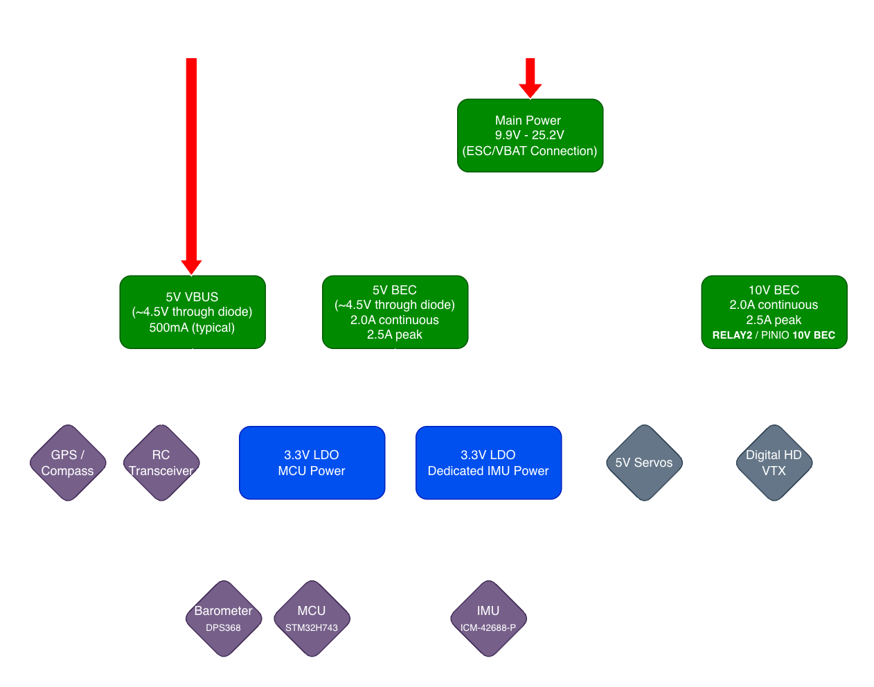 Power Flow on USB or Battery
Input Power
Voltage Specifications
| Parameter | Specification | Notes |
|---|---|---|
| Input Voltage Range | 9.9V-25.2V | 3S-6S LiPo (usable pack range) |
| Recommended | 14.8V-25.2V | 4S-6S LiPo (most common use) |
| Absolute Maximum | 28V | Do not exceed; risk of regulator damage |
| Absolute Minimum | 8V | Below this, flight controller power is not guaranteed; VTX voltage will track battery voltage |
Voltage Limits: Do not exceed 28 V input. Operation above this may permanently damage the regulators and destroy the board. On the low side, the regulators remain enabled down to ~8V. This is below the absolute 3.0V/cell minimum on 3S packs — while the system may still power in an emergency, operation in this region places severe stress on the battery and can cause permanent damage.
Power Input Connection
Primary Power Input: ESC Connector (8-pin JST-SH) - See ESC Connector Pinout for complete pin assignments
- Pin 1: VBAT (Battery positive, 9.9V-25.2V)
- Pin 2: GND (Battery negative, common ground)
Connection Methods:
- Via 4-in-1 ESC (Recommended)
- Use included JST-SH ESC cable
- ESC provides battery power to FC
- ESC current sensor provides analog signal to Pin 3 (typically present on 4-in-1 ESCs)
- ESC UART telemetry on Pin 4 (optional; requires ESC firmware/hardware support — see ESC Telemetry Methods)
- Direct Battery Connection (Alternative)
- Solder battery leads directly to ESC connector pads
- Use for standalone FC testing or non-ESC applications
- Requires external current sensor for telemetry
Reverse Polarity Protection
Limited Reverse Polarity Protection: The H7-Digital has NO reverse polarity protection on the main power input. Connecting battery backwards will cause immediate and permanent damage. Always double-check polarity before connecting power.
Protection Best Practices:
- Use pre-wired ESC cables (JST connectors prevent reverse connection)
- Mark polarity clearly on custom cables
- Use a multimeter to verify polarity before first connection
- Consider adding external diode or dedicated reverse-polarity module for critical applications
Voltage Regulators
For complete BEC electrical specifications, see Specifications - Power System.
This section covers practical power planning, current budgeting, and wiring guidance.
5V BEC - Current Budget Planning
5V BEC Rating: 2.0A continuous, 2.5A peak (< 10 seconds)
5V Powers:
- Flight controller MCU and logic (via onboard 3.3V LDO)
- GPS module (via GPS connector)
- RC receiver (via RC INPUT connector)
- Servos (via SRVO connector)
- External I2C compass (via GPS connector)
- Onboard sensors (IMU, barometer)
| Device | Typical Current | Peak Current | Connector |
|---|---|---|---|
| H7-Digital Logic | 150mA | 200mA | Internal |
| GPS Module | 50-80mA | 100mA | GPS connector |
| RC Receiver | 30-50mA | 80mA | RC INPUT |
| Servos (2x) | 200-500mA | 1000mA+ | SRVO |
| Compass | 10mA | 15mA | GPS connector (I2C) |
| Reserve | - | 200mA | Safety margin |
| TOTAL | ~600mA typical | ~2A peak | - |
Servo Current Draw: High-torque servos under load can draw 500mA+ each. Two servos at full load can approach or exceed the 2.5A peak limit. For demanding servo applications, consider:
- Using low-current digital servos
- Adding external BEC for servo power
- Limiting servo speed/torque in firmware
Reducing Servo Noise: For applications with high servo current draw, add a 470–1000µF low-ESR capacitor (≥10V rated) across the servo power pins (5V and GND) as close as possible to the SRVO connector. This capacitor acts as a local energy reservoir to absorb millisecond-scale current spikes during servo motion, preventing voltage sag and reducing electrical noise coupling into the flight controller. Use a polymer or low-ESR electrolytic capacitor for best performance, and add a 0.1µF ceramic capacitor in parallel for high-frequency filtering.
10V BEC - VTX Power Management
10V BEC Rating: 2.0A continuous, 2.5A peak (< 10 seconds)
Software Control: GPIO PE2 (RELAY2 GPIO 80 / PINIO1 10V BEC)
Powers:
- Digital HD VTX ONLY (via VTX connector)
10V is VTX ONLY: The 10V output is designed exclusively for digital HD video transmitters (OpenIPC, DJI, Walksnail, HDZero). DO NOT connect 5V peripherals to the 10V rail. Damage will occur immediately.
The 10V rail requires VIN ≥ ~10.5 V to regulate; below this it tracks VIN (pass-through).
Compatible Digital VTX Systems:
- ✓ OpenIPC (most require 9-22V)
- ✓ DJI Air Unit / Vista (7-26.4V range)
- ✓ Walksnail Avatar / VRX (9-25V range)
- ✓ HDZero VTX (typically 7-25V range)
Typical VTX Current Draw:
- Idle: 200-400mA
- Transmitting: 600-1400mA (depends on system and TX power)
- All common digital VTX systems compatible within 2.0A continuous rating
Check your specific model’s datasheet; input ranges and typical/peak current draw vary.
3.3V LDO Regulators (Onboard)
The H7-Digital features two independent 3.3V LDO regulators for clean, isolated power:
3.3V MCU Power Rail
Specifications:
| Parameter | Value |
|---|---|
| Output Voltage | 3.3V |
| Continuous Current | 1.0A |
| Input Source | 5V BEC or USB (auto-select) |
Powers:
- STM32H743 microcontroller
- Onboard status LEDs
- SD card interface
- DPS368 barometer
3.3V IMU Isolated Power Rail
Specifications:
| Parameter | Value |
|---|---|
| Output Voltage | 3.3V |
| Continuous Current | 250mA |
| Input Source | 5V BEC or USB (auto-select) |
| Noise Performance | Ultra-low noise, high PSRR |
Powers:
- ICM-42688-P IMU only (isolated for noise immunity)
Why Isolated IMU Power? The ICM-42688-P gyroscope is extremely sensitive to power supply noise. Digital switching noise from the STM32H743 MCU can couple into the IMU power rail and appear as false vibrations in sensor readings. A separate, ultra-low-noise LDO with high PSRR ensures the cleanest possible power delivery to the IMU, improving flight performance and reducing “noise floors” in Blackbox logs.
VTX Power Control (Software-Controlled 10V)
Control GPIO
Pin: PE2 (GPIO 80 in ArduPilot, PINIO1 in Betaflight)
Default State: ON (HIGH) - 10V enabled at power-up
ArduPilot Configuration
RELAY2 is pre-configured in the H7-Digital firmware:
// Pre-configured in hwdef.dat:
RELAY2_PIN_DEFAULT = 80    (GPIO PE2)
RELAY2_DEFAULT = 1         (ON at startup)
To Control via RC Switch:
Assign the Relay2 On/Off function to any RC channel (e.g., channel 7):
RC7_OPTION = 34 (Relay2 On/Off)
Save parameters and flip the channel 7 switch to control VTX power.
Mission Command Control (Advanced):
- Use
DO_SET_RELAYcommand in autonomous missions - Relay Number: 2
- Setting: 0=OFF, 1=ON
Pre-configured: RELAY2 is already mapped to GPIO 80 in firmware (see Specifications - VTX Power Control). No manual
RELAY2_PINconfiguration needed - just assign an RC channel switch.
Use Cases:
- Power off VTX during ground operations (save battery)
- Disable VTX for regulatory compliance (RF off zones)
- Power cycle VTX without full reboot (troubleshooting)
- Automated VTX control in missions
Betaflight Configuration
PINIO1 is pre-configured in the H7-Digital firmware target with the following settings:
// Pre-configured in firmware:
PINIO1_BOX = 40        (User 1 box mode)
PINIO1_CONFIG = 129    (Output mode, default HIGH)
BOX_USER1_NAME = "10V BEC"
resource PINIO 1 E02
To Control via Switch:
- Go to Modes Tab in Betaflight Configurator
- Add “10V BEC” mode (appears as “User 1” or “10V BEC”)
- Assign to auxiliary channel switch (e.g., AUX1-4)
- Save and reboot
Pre-configured: Unlike most boards, the H7-Digital firmware has PINIO1 already mapped to GPIO PE2 with “10V BEC” naming. No CLI commands needed - just assign a switch in the Modes tab.
Use Cases:
- Power off VTX in pit area
- VTX power cycle via OSD menu
- Switch-controlled VTX enable/disable
Protection Features
Current Ratings:
- Continuous: 2.0A
- Peak: 2.5A (< 10 seconds)
Best Practices:
- Keep continuous current draw ≤ 2.0A for optimal reliability
- Brief peaks to 2.5A are acceptable (VTX boot, mode changes)
- Ensure adequate airflow around flight controller for thermal management
VTX Selection: Most digital VTX systems draw 0.8-1.4A during transmission, well within the 2.0A continuous rating. Choose VTX with ≤ 2A peak current for best compatibility. Allow 5-10 seconds for VTX boot before arming.
Battery Monitoring
Voltage & Current Sensing
Voltage Input: PA0 (ADC1 Channel 16)
- Voltage divider ratio: 11:1
- Measurement range: 0-26V (covers 6S LiPo)
Current Input: PA1 (ADC1 Channel 17)
- Scaling: 18mV/A (from ESC current sensor)
- Typical range: 0-180A (depends on ESC sensor)
ArduPilot Configuration
BATT_MONITOR = 4           (Analog Voltage and Current)
BATT_VOLT_PIN = 16         (PA0 = ADC channel 16)
BATT_CURR_PIN = 17         (PA1 = ADC channel 17)
BATT_VOLT_MULT = 11.0      (Voltage divider ratio)
BATT_AMP_PERVLT = 18.0     (Current sensor scaling)
Calibration Procedure:
- Voltage Calibration:
- Measure actual battery voltage with multimeter
- Compare to GCS reported voltage
- Adjust
BATT_VOLT_MULTif needed:New_VOLT_MULT = Old_VOLT_MULT × (Multimeter_Voltage / GCS_Voltage)
- Current Calibration:
- Use known current draw (e.g., bench power supply)
- Compare to GCS reported current
- Adjust
BATT_AMP_PERVLTif needed:New_AMP_PERVLT = Old_AMP_PERVLT × (Actual_Current / GCS_Current)
Betaflight Configuration
Power Tab:
- Voltage Meter Source: Onboard ADC
- Battery Cells: Auto-detect or manual (3S/4S/5S/6S)
- Voltage Scale: 110 (default for 11:1 divider)
- Current Meter Source: Onboard ADC
- Current Scale: 180 (default for 18mV/A sensor)
Calibration:
- Connect battery and power on
- Measure battery voltage with multimeter
- Adjust “Voltage Scale” until Configurator matches multimeter
- Use known current source or ESC calibration for current scale
Current Sensor Source: The current sensor input (Pin 3 on ESC connector) receives an analog signal from the ESC onboard current sensor. If your ESC does not have a current sensor, current monitoring will not function. Voltage monitoring works independently.
4-in-1 ESC Current Monitoring: On 4-in-1 ESCs, the analog Pin 3 input (total pack current via shared shunt) is the only reliable way to monitor current. UART telemetry and EDT current frames are per-motor and don’t work on shared-shunt 4-in-1 hardware. Individual standalone ESCs with per-ESC current sensors can report current via UART or EDT.
Low Battery Warnings
ArduPilot:
BATT_LOW_VOLT = 14.0    (4S: 3.5V/cell)
BATT_CRT_VOLT = 13.2    (4S: 3.3V/cell)
BATT_LOW_MAH = 3000     (mAh consumed before warning)
BATT_CRT_MAH = 3500     (mAh consumed before critical)
Betaflight:
- Warning Cell Voltage: 3.5V/cell
- Critical Cell Voltage: 3.3V/cell
- Capacity Warning: mAh threshold
Power Distribution to Components
Component Power Map
| Component | Voltage | Current | Source | Connector |
|---|---|---|---|---|
| STM32H743 MCU | 3.3V | 150mA | 5V BEC → 3.3V LDO | Internal |
| ICM-42688-P IMU | 3.3V | 5mA | 5V BEC → Isolated 3.3V LDO | Internal |
| DPS368 Barometer | 3.3V | 1mA | 5V BEC → 3.3V LDO | Internal |
| GPS Module | 5V (4.5V via USB) | 80mA | 5V BEC or USB | GPS connector Pin 1 |
| External Compass | 5V (4.5V via USB) | 10mA | 5V BEC or USB | GPS connector I2C |
| RC Receiver | 5V (4.5V via USB) | 50mA | 5V BEC or USB | RC INPUT Pin 1 |
| Servos (S1/S2) | 5V | 500mA+ | 5V BEC (battery only) | SRVO Pin 1 |
| Digital VTX | 10V | 1000mA+ | 10V BEC (battery only) | VTX Pin 1 |
| SD Card | 3.3V | 50mA | 5V BEC → 3.3V LDO | Internal |
USB vs Battery Power: Through diode protection, 5V peripherals typically see no less than ~4.5V (within 5V tolerance) whether powered from USB or battery. The 5V servo connector and 10V VTX connector bypass this diode and are battery-only (not powered from USB). See Power - Power Flow Diagram.
Power Wiring Best Practices
Wire Gauge Recommendations
| Connection | Current | Recommended Gauge | Notes |
|---|---|---|---|
| Battery to ESC | >60A | 12-14 AWG | As short as possible |
| ESC to FC (VBAT) | <5A | 22-24 AWG | Standard JST-SH pre-wired cables (< 30mm) |
| 5V Peripherals | <2A total | 24-28 AWG | ≤30cm |
| 10V VTX | <2A | 22-26 AWG | ≤20cm |
| Signal Wires | <100mA | 26-30 AWG | ≤30cm |
Short Wire Ampacity: Standard ESC-to-FC connector cables use 22-24 AWG wire at < 30mm length. At this short distance, 22-24 AWG easily handles 5A+ due to excellent heat dissipation and negligible voltage drop. Pre-wired JST-SH cables are appropriately sized.
Connector Types & Wiring
ESC to FC Connection:
- Use JST-SH 8-pin (included)
- Pre-wired ESC cables prevent polarity mistakes
- If soldering directly, use heat-shrink and label polarity
Troubleshooting Power Issues
No Power to Flight Controller
Symptoms: No LED lights, no USB connection, completely dead
Check:
- ✓ Battery voltage (use multimeter on battery directly)
- ✓ VBAT and GND on ESC connector (check continuity to battery)
- ✓ Polarity (VBAT on Pin 1, GND on Pin 2)
- ✓ Fuse or inline switch (if used)
- ✓ Battery connector/XT60 integrity (solder joints, crimps)
Possible Causes:
- Dead/discharged battery
- Reversed polarity (if previously connected backwards → board likely damaged)
- Broken solder joint on power connector
- Damaged voltage regulator (if previously overvolted)
Brownouts During Flight
Symptoms: FC reboots mid-flight, sudden loss of control, log shows voltage sag
Check:
- ✓ Battery capacity (undersized battery for application)
- ✓ Battery C-rating (insufficient discharge rate)
- ✓ Wire gauge (voltage drop on thin wires)
- ✓ Connector resistance (XT60/ESC connectors damaged or loose)
- ✓ Battery age/health (internal resistance increased)
Solutions:
- Upgrade to higher capacity or higher C-rating battery
- Use thicker battery-to-ESC wires (reduce voltage drop)
- Replace worn XT60 connectors (high resistance)
- Set
BATT_LOW_VOLThigher to prevent deep discharge
VTX Not Powering On
Symptoms: No video feed, VTX LEDs off, cold to touch
Check:
- ✓ 10V output enabled (check GPIO PE2 state in GCS or OSD)
- ✓ VTX connector wiring (Pin 1 = 10V, Pin 2/5 = GND)
- ✓ VTX voltage rating (confirm VTX accepts 10V input)
- ✓ 10V BEC overcurrent shutdown (thermal protection)
Solutions:
- Enable 10V output via RELAY2 (ArduPilot) or PINIO1 (Betaflight)
- Verify VTX voltage range (some VTX require 7-12V, others 5V only)
- Check VTX current draw (if >2.5A, may trigger overcurrent protection)
- Allow airflow over FC for BEC cooling (thermal shutdown recovery)
Insufficient Current for Peripherals
Symptoms: Peripherals resetting, servos jittering, GPS losing lock
Check:
- ✓ Total 5V current draw (see current budget table)
- ✓ Servo peak current (measure with current clamp if possible)
- ✓ Multiple high-current devices on one connector
Solutions:
- Add external 5V BEC for servos (offload from FC BEC)
- Use lower-current servos or limit servo speed/torque in firmware
- Remove non-essential peripherals
Power Consumption Estimates
Typical Build Power Budget
Example 5” Freestyle Quad (4S Battery):
| Component | Voltage | Current | Power |
|---|---|---|---|
| H7-Digital FC | 5V | 150mA | 0.75W |
| RC Receiver (ELRS) | 5V | 40mA | 0.2W |
| GPS + Compass | 5V | 80mA | 0.4W |
| DJI Air Unit | 10V | 1200mA | 12W |
| 4x Motors (hover) | 16.8V | 8A total | 134W |
| TOTAL (hover) | - | - | ~147W |
Flight Time Estimate (1300mAh 4S battery):
- Battery capacity: 1300mAh × 14.8V = 19.24Wh
- Average consumption: 147W (hover) to 400W+ (aggressive flight)
- Flight time: 3-6 minutes depending on flight style
Related Documentation
- Pinout & Connectors - Power connector pinouts and GPIO pin assignments
- Specifications - Complete power system specifications
External Resources
- ArduPilot Battery Monitoring - Official calibration guide
Support
For power system questions:
- Email: support@aerocogito.com